
A Semi-automatic Displacement Recorder
Professor of Civil Engineering,
Middle East Technical University, Ankara, Turkey.
E-mail: mirata@metu.edu.tr
TECHNICAL NOTE
|
|
A Semi-automatic Displacement Recorder
Professor of Civil Engineering,
|
||
|
TECHNICAL NOTE |
A semi-automatic displacement recorder (sadir), a simple device for recording displacements up to 50 mm, by making pencil marks on a probe, is described. The distance between such marks has afterwards to be measured using a mm scale; this limits the accuracy of such measurements to about 0.2 mm. The device has been made by simple tools, using improvised materials, and is presented as an example of possible alternative designs. Three of such devices have been made, calibrated against a dial gauge, and used uccessfully in a prismatic wedge shear test. An improved, modified version is also described.
KEYWORDS: displacements, laboratory equipment, recorder, semi-automatic, shear test, wedge shear test.
If the fairly expensive electronic devices for automatic recording of displacements are set aside, dial gauges are practical and accurate means of measuring displacements for most shear strength tests on soils, and so also for the wedge shear test (Mirata, 1991; Mirata et al., 1998, 1999). No problem arises, so long as someone is available to aid in reading the three dial gauges needed for the rigorous evaluation of all three versions of the latter test. If, however, one desires to perform the test without such assistance, and without interrupting the loading, a semi-automatic means of recording displacements can be useful. In recording the various displacements in this test, there is no need for an accuracy of 0.01 mm, as offered by a 50 mm capacity dial gauge; nor for an accuracy of 0.1 mm, as obtained in practice because of the difficulty of reading all dial gauges simultaneously. This has been substantiated by rounding off all such displacements to the nearest 1 mm in typical wedge shear tests (the first files in each of Boxes 4.1, 4.2 and 4.3 given by Mirata, 2000), and re-evaluating the results. The difference in the shear strength parameters output, summarized in Table 1, was negligible. So a simple device whereby the displacements could be recorded to the nearest 0.2 mm by pressing an electrical button would facilitate the test without impairing its accuracy. Three such devices have been made using improvised materials, and simple tools like a drill, a vice, sawing and cutting tools, round-nose pliers, and tweezers. These semi-automatic displacement recorders (sadirs) have been tested against a dial gauge, and used successfully in a prismatic wedge shear test. One sadir was subsequently modified to advantage.
Table 1. Differences in wedge shear test
results on rounding off displacements to 1 mm
| Type of wedge shear test |
Material tested | Initial shear plane area (cm2) |
Cohesion (kPa) Displacements Displacements as measured rounded off |
Angle of friction (o) Displacements Displacements as measured rounded off |
| In situ | Unsaturated, stiff fissured clay |
900 | 5.00 5.03 | 36.77 36.76 |
| Prismatic | Dense, well graded gravel |
900 | ... ... | 48.02 47.98 |
| Cylindrical | Unsaturated, stiff fissured clay |
116 | 21.70 21.62 | 30.16 30.17 |
The requirements for such a device may be enumerated as follows.
DESCRIPTION OF THE FIRST VERSION
The device which has been made first is shown in Fig. 1. E is a disused electromagnetic switch (labelled 'AMERICAN ZETTLER, 24VDC 526 AZ421-70-10L'), designed for closing four different circuits while opening four others on being operated on 24 volts dc. As far as the present device is concerned, it imparts a forward movement of about 0.3 mm to the top of the portion marked T; a spring returns T to its original position on switching off the current. Embedded in the 124 mm x 58 mm x 14 mm softwood board B, E is fixed in position by means of the screw S1.
Figure 1. The first version of the semi-automatic displacement recorder (sadir)
H is one half of a cheap pair of compasses, and is used to hold and adjust the soft pencil N. In place of the other half of H, the perforated portion of a plastic tea stirrer S (see Appendix, Note 1) has been tightly screwed; the other, curtailed end of S passes through the slit cut in the hardwood peg P, the lower end of which is cylindrical and fits an 8 mm dia. hole in the board B; the upper end of P has a screw S2 for tightening S in position. After adjustment in vertical and horizontal planes, P can be fixed in position by means of the screw S3, which is also used for fastening the electrical leads soldered to the terminals of E. To reduce its bending resistance, the section of S has been thinned to about 0.7 mm, at a point close to P.
The probe R is an exhausted ball-point pen, measuring 7.5 mm across the flats of its hexagonal cross-section, around which has been wrapped a sheet of 150 mm x 150 mm x 0.2 mm paper, plus two turns of a 0.1 mm thick paper to bring it to about 0.4 mm less in dia. than the inner dia. of 9.8 mm of one third of a disused rapidograph holder G, a smooth surfaced plastic tube, tightly fitting a hole in B. The sheets of paper, wrapped around R, are about 5 mm proud of the top of R. Spaced at 120o around the protruding portion of the wrapped paper have been cut three slits through each of which passes a 0.4 mm dia. elastic thread ET, extracted from a 110 mm length of textile covered elastic cord (Note 2). ET is tied on the cap C of the probe R at the upper end, and on to a miniature hook, bent out of silver amalgamated 0.7 mm dia. wire at the lower end (Note 3). After the device is adjusted in position for recording displacements, these hooks are passed through the U-shaped nails U (alternatively, eye screws may be used ), driven into B at 120o intervals around G. Across the range of travel of the tip of the pencil N, has been glued a 126 mm x 8 mm x 0.2 mm strip of paper along 2.5 mm of one of its long sides, the rest being free to act as a springy flap F, ensuring that the tip of N makes a mark on it, regardless of the small lateral displacements of the probe during use. The movable part T of the electromagnet E is connected to the pencil holder H by means of a perspex straddle SR to which grooves of the right size, in the right position have been carefully cut; having made sure that SR fits the opening on T, and straddles the holder H, it was glued on these components (Note 4). The bracket BR, cut out of a 1.5 mm thick brass strip enables the device to be mounted on the same type of support as used for dial gauges. The completed device weighed 122 g, less than half the mass of two different makes of 50 mm capacity dial gauges, found to weigh 250 g and 291 g.
Marks made on the flap of the probe of three sadirs at 100 x 10-2 mm reading intervals of a dial gauge, all bearing on the same platen of a compression machine, gave a factor of 1.01 for converting the distances between the marks on the sadir probe, measured using a mm scale, into mm of actual displacement given by the dial gauge. The 1 % difference between true displacements, and those recorded by sadir is due to the gradually increasing pull of the elastic threads on the device, as displacement increases (a maximum force of about 0.12 N has been measured at a displacement of 50 mm), whereas, such a force (fluctuating around 0.09 N) is practically independent of displacement in the case of dial gauges. The probe R can be easily removed, and all three devices including the central push-button switch and electrical leads stored in a cardboard box, measuring no more than 370 mm x 260 mm x 60 mm. These devices have been successfully used in a prismatic wedge shear test (Fig. 2) on a dense sand, performed in collaboration with Mr. Y. Erzin. This was rather an extreme type of material for testing such devices, in that the strength built up rapidly to the peak value at a shear displacement of 5.1 mm; so, the first few marks on the sadir probes overlapped, but both the overall shape of the shear stress versus shear displacement curve and the peak and ultimate strengths obtained closely matched those in a repeat test by Mr. Erzin, on the same sand at the same density and under the same lateral load, but using dial gauges for measuring displacements (the angles of friction at peak and ultimate strength in the former test were 51.05o and 37.70o and in the latter 51.32o and 37.85o respectively).
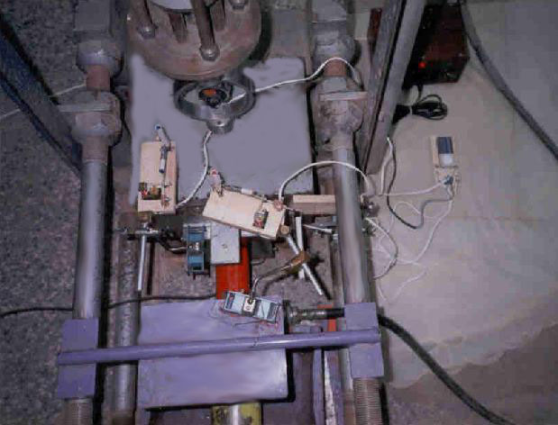
Figure 2. Use of three sadirs in a prismatic wedge shear test
To eliminate the drawbacks of the device shown in Fig. 1 that (a) it is rather long, and so the moments induced due to the extension of the elastic threads during use cause a measurable deflection of the device; (b) the plastic support S for the pencil holder tends to creep to eventual failure within a few months, the following modifications were made. The rightmost 28 mm of the board B (Fig. 1) was cut off, and glued on the left-hand end of B; the next 40 mm on the right was cut off and discarded. The length of the board B was thus reduced to 84 mm, as shown in Fig. 3. An access hole A was drilled on the left, for the screw S1; the U-shaped nails U were shifted by 60o. The nail NL carrying a wing WG ( Note 5) was then driven into B, in such a position as to enable the tip of the soft pencil core, held in the bent upper portion PH of WG, to touch the flap F of the probe, described earlier. WG was connected to the movable top T of the electromagnet E by a piece of wire W. The position of the support bracket BR was shifted as in Figure 3. Tested in a similar way as before, the conversion factor for the distances recorded by this version of sadir was found to be 1.00; The mass of the device was reduced to 84 g. The only disadvantage of this version compared to that in Fig. 1, is the somewhat increased difficulty of adjusting the pencil core, but this seems to be outweighed by its advantages of being more compact, and free from creep effects.
Figure 3. The modified version of sadir
Where funds exist, electronic data logging devices are presently available. If an assistant is available, the use of dial gauges is a cheaper alternative for measuring displacements. If the shear test has to be carried out without such assistance, and without interrupting the loading, simple devices such as those described may provide a solution. Three such devices have been successfully used in a prismatic wedge shear test on dense sand, and shown to be able to record displacements up to 50 mm with an accuracy of 0.2 mm. A modified version has yielded an improved calibration factor.
Thanks are due to technicians A. Bal and I. Özdemir for help in making the devices described, to Mr. C. Erduygun for providing the electromagnets, and to Mr. M. Ekinci for the tracings.
The details of some of the operations involved in making the sadir, and the various drawbacks discovered subsequently are noted below.
NOTE 1. The material of the plastic stirrers has proved not to be the best for the purpose: the tip of the pencil was discovered to have crept downwards, when stored for some days, and the plastic components eventually fractured at the point where they had been thinned. A better material to use for this purpose, if this design is to be adopted, is probably a thin flexible metal strip.
NOTE 2. An easy way to recover the elastic threads from a textile covered cord, is to fix the cord in a vice, with only about 0.3 mm of its cross section protruding, and cut the textile covering with a razor blade along its protruding edge. The operation can then be repeated on the next uncut portion of the cord. The recovered threads are then dipped in talcum powder to prolong their useful life. Elastic threads treated in this way were found to be still performing well some eight months after extraction.
NOTE 3. The use of tweezers facilitates the making of the knots at the ends of such a short length of elastic. Having tied the ends, the free length of the elastic threads ranged between 54 and 64 mm. As these could be extended by about 2.5 times their free length, they were brought to about 3.2 mm free length by winding each on a tiny piece of wood, and clamping by means of a wire clip CL (Fig. 1). As such knots and clamps tended to become undone with time, they were reinforced by a spot of glue.
NOTE 4. Less restraint might have been imposed on the electromagnet, had SR been glued just on to T, leaving the other end to act as a pivot.
NOTE 5. The wing WG (Fig. 3) was made as follows. A rectangular sheet measuring about 42 mm x 40 mm x 0.3 mm was cut out of the sealing flap of a tennis ball can. This was placed on a vice, with the 40 mm side parallel to the gap of about 3.5 mm of the vice, with about 14 mm protruding from one side of the gap; a 52 mm long, 2.5 mm dia. nail was laid on the sheet, above the gap, and hammered into the gap until about 0.3 mm of the nail was proud of the non-indented part of the sheet. The top of the wing was cut along the left edge of the indent for about 10 mm; the indented width and the upper 7 mm of the right-hand portion were cut off and discarded; the remainder was bent over the rest of the wing. The left-hand portion of the top was bent over the wing, and up again, forming the holder PH for the core of a soft pencil, and the upper end left protruding above the top of the wing to act as a lever for slackening PH during adjustment of the pencil. To enhance the grip between the pencil core and the holder, tissue paper was glued on the inner face of PH. Two notches, spaced at about 22.5 mm, were filed around the 52 mm long, 2.5 mm dia. nail NL, starting from about 10 mm from the head; a pair of tiny holes were punched on either side of the indent on the wing, in line with each of these notches, and the wing tied on to NL by the 0.7 mm wire WR (Fig. 3) in such a way as to enable it to rotate through a reasonable angle with a minimum of friction, and no perceivable backlash.
1. Mirata, T. (1991). Developments in wedge shear
testing of unsaturated clays and gravels.
Géotechnique 41, No. 1, 79-100. Corrigenda: Géotechnique
41, No. 2, 296; 41, No. 4, 639.
2. Mirata, T. (2000). Manual for Wedge Shear Testing of Soils. 170 pp. Obtainable from ULAKBIM (Turkish Scientific & Technical Documentation Centre); contact Mrs. C. Yazicioglu at: cevza@ulakbim.gov.tr or ulakbim@gov.tr
3. Mirata, T., Gökalp, A., and Sakar, M. (1998).
Achieving higher normal stress levels in the
prismatic wedge shear test. EJGE
Paper 9804.
4. Mirata, T., Varan, M., Seçkin, A., and
Gün, F. (1999). Applications of the cylindrical wedge shear
test to the study of shear strength of compacted clays.
EJGE Volume 4, 1999.
| © 2002 ejge | |