| |

|

|
Shotcreting and its Adhesion Strength
by
Dheeraj Kumar
Research Scholar, Mining Department, Indian Institute of Technology, Kharagpur, India
e-mail
P. K. Behera
Deputy Director, National Institute of Rock Mechanics, Champion Reef, KGF, Banglore. India
U. K. Singh
Professor, Mining Engineering Department, Indian School of Mines, Dhanbad, India
|
Abstract
In the present trend of support system used in underground coal-mines, shotcrete is gaining wide acceptance particularly in Tunnel linings. The shotcrete support efficacy depends on the adhesion strength i.e. bonding between shotcrete and the rock surface. In order to determine the Bond Strength of shotcrete to rock surface, an instrumental setup has been devised. The different coal measure rocks like shale, sandstone (coarse, medium, fine grained) were acquired from various mines.
A thorough laboratory study of adhesion of shotcrete to same rock with different surfaces roughness shows that roughness of the rock surface play a more significant role in Bond Strength, for a particular range of JRC between 8 to 17. For a particular range of JRC Bond Strength is strongly correlated to JRC. The result also showed that tensile strength of rock has no relationship with Bond Strength. For a perfect bonding minimum setting time of shotcrete mixture is found to be 21 days. It was further investigated that the use of some accelerating material becomes significant in order to achieve full Bond Strength at the earliest. A minimum of five days is required to get an early setting of the shotcrete. The practical consequences of the investigation are also discussed.
Keywords: Mining, Lining, Bond Strength, Shotcrete
Introduction
The term "Bond Strength of Shotcrete" may be defined as ability of shotcrete to adhere to a particular surface. The fact that all primary failure occurs due to the low tensile adhesion strength between shotcrete and rock surface makes it interesting to find out the adhesion strength that can be expected from different rock types and what factors influence the adhesion.
Two types of bond strength must be considered for shotcrete: tensile and shear. Tensile bond strength is a measure of the ability of shotcrete to remain in contact with the rock when a tensile stress is applied normal to the rock-shotcrete interface. Shear bond strength is concerned with the ability to resist stresses that act parallel to the rock ‑ shotcrete interface. In an actual shotcrete lining there is some combination of these stresses acting on the shotcrete‑rock interface.
The adhesion test should be a widely used tool for the design of shotcrete linings.‑If the adhesion is expected to be bad a solution which does not require any adhesion strength should be chosen, i.e. bolt supported reinforced shotcrete or arches with end supports. On the other hand if the adhesion is expected to be good simple solutions as for example thin reinforced linings or arches without end supports may be chosen.
The shotcrete adhesion or bond to the ground increases with time, provided that the ground is firm, clean and dry. Adhesion to smooth, wet and soft ground is generally poor. Even though infect shotcrete is essentially impervious, shooting against running water on the ground surface can remove shotcrete cement particles and leave a permanent erosion path with little or no bond.
Adhesion to hard dry granite family rock can reach 1.4 MPa but can be almost zero in soft damp ground damp ground. Adhesion depends first and foremost on the rock quality and the cleanliness of the rock surface. The total bearing capacity increases somewhat with increasing thickness of shotcrete (Stille,1992).Shrinkage cracks will tend to reduce bond ; the steel fibres in SFRS inhibit this shrinkage cracking and SFRS generally shows superior bond compared to conventional shotcrete.
Few earlier studies Slate and HSU and Barbo (1964) exists."mso-spacerun: yes"> A pilot study on the adhesion strength of different rock was made by them. The results were difficult to interpret due to there great spreading. Therefore it was found necessary to make a similar test under controlled circumstances and limit the investigation to four of the most important factors as a first step.
Approach
Investigations are carried out to determine the effect of the following factors on bond strength
For the purpose different coal measure rocks like coal, shale fine grained sandstone, medium grained sandstone, and coarse grained sandstone (approx. size 40 X 30 cm) were acquired from different mine.
To separate the influence of the roughness from that
of the strength of the rock, different roughness surface were induced by
breaking the same rock sample into few pieces.
To separate the effect of time from that of the
strength and roughness, Bond strength were determined on the same sample with
smooth surface (JRC=1), under different time interval.
To investigate effect of accelerator on bonding
strength under different time interval, bonding strength were determined on
same rock sample with JRC =1(planer surface, smooth) under varying time by
adding 5% sodium silicate to shotcrete mixture.
Materials for sample preparation
A typical design of wet mix used in sample preparation for Bond Strength test is given in table 1.
Table 1. Mix design of Steel Fibers Reinforced Shotcrete
Used in sample preparation for bond Strength test.
|
| Material |
Unit |
Wet mix amount |
|
| Natural sand |
kg |
4.3 |
|
Crushed aggregate
(5 - 10 mm) |
kg |
5-7 |
|
| Cement, L & T |
kg |
2.5 |
|
| Silica fumes |
kg |
.30
|
|
| Steel fiber/Dramix. 30/0.50 |
kg |
.30
|
|
Accelerator, Sodium
Silicate |
% |
5
(by weight of cement) |
|
| W/C Ratio |
Ratio |
.45 |
|
| Density |
k/m3 |
60 |
|
Design and Fabrication of Bond Strength tester.
As mentioned an equipment was developed for the determination of bond strength of shotcrete to the rock surface. Figure 1 shows Bond strength tester holding the sample. It consists of following components.
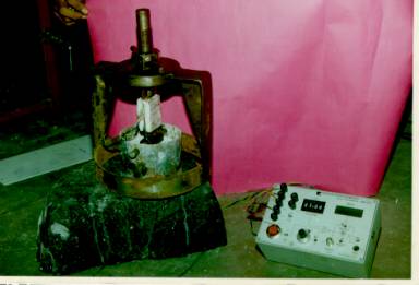
Figure 1. Experimental Setup for the Bond Strength test
Main frame:
Made up of Mild steel, plate with a base ring. A provision is made to apply a pull load on the shotcrete molded in a mild steel pipe mould of 4" diameter & 3.5" height, on the rock surface (Figure 2).
Figure 2. Bond Strength tester
Load transducer plate
Two pairs of strain gauge (G.F. 1), (one pair for axial deformation and other for lateral deformation) are mounted on the plate. At the lower end of the plate a provision is made to hold the mould through a pin passing centrally to it. The upper end is attached to the screw of the main frame through a pin.
Digital strain meter
The DIVID 20A, a digital strain meter, specially designed for the connection of strain gauge full bridges or half bridges were used for the purpose of recording deformation corresponding to the pull load applied. A correlation between pull load (kg) and strain gauge reading (mv) is made.
The calibration factor achieved as 2 mv = 1 kg.
Editor's Note. This paper uses the old metric (not SI) units; whenever the unit name kg is used here in a force (or weight) measurement it should be understood as the weight of 1 kg mass on earth, or 9.8 Newtons
X - Y Recorder
It was a Houston instruments (USA) make, series 2000, Omnigraphic The amplified signals were received from the digital strain meter in mv. The scale of X‑Y recorder was set such a way that its pen traversed 1 cm along X axis for a strain meter reading of 20 mv.
Experimentation on Bond Strength
Sample preparation
The rock surface on which shotcrete was to be sprayed, were cleaned properly. As far as possible new fresh surface were used. Before spraying of shotcrete on rock surfaces., the surface profiles were plotted on the computer using Data Acquisition system with the help of LVDT and Potentiometer and rock joint roughness coefficient (JRC) were calculated using the roughness profiles. Properly mixed shotcrete mixtures were sprayed (using the spraying gun) in moulds kept on the rock surfaces. The thickness of shotcrete cast was kept constant. As far as possible the inherent moisture content of the mixture was protected.
Curing
For the curing of the samples same procedure was adopted as for the concrete, because most documents indicate that shotcrete should be treated according to the same rules as those for normal concrete. To prevent dehydration at the contact surface, the cottons properly wet were kept all around the mould at the base. The normal time
required for curing varied between 3 and 7 days.
Test procedure:
The Bond strength tester was attached to mould in such a way that a pull could be applied centrally to the casted sample mould (Figure 3). The connection of strain-gauge wire to the strain meter in a full bridge circuit was made."mso-spacerun:
yes"> The strain indicator was switched on and the reading was brought to o zero through the balance knob. The X ‑ Y recorder was connected to the strain meter and to the supply voltage, and switched on. The pointer pen of X ‑ Y recorder was brought to zero position. The pull load was then applied gradually by turning the screw nut handle clockwise. The load at which the bond failed was recorded on X ‑ Y plotter. The bond surface area was also measured.
The test for effect on roughness and tensile strength were carried on 14th day of casting.
The test for effect of accelerator was carried with an interval of one day by adding 5% sodium silicate to the shotcrete mixture while casting.
At an interval of 7 days, the tests were carried out to find out the effect of time on bond strength of shotcrete.
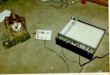
Figure 3. Complete setup for Tension Adhesion Test.
Results and analysis
Table 2 shows estimated joint roughness coefficient by slope parameter (Z2). Different types of rocks were chosen and the surface roughness was determined along two directions X and Y, perpendicular to each other.
Table 2. Estimated JRC by slope parameter (z2) for different rock sample
|
| ROCK SAMPLE |
ROCK TYPE |
Z2 ( X) |
Z2 ( Y) |
JRC (X) |
JRC (Y) |
|
| |
|
|
|
|
|
| RI |
fined grained sst |
.2781 |
.3189 |
15.550 |
18.72 |
| R2 |
medium grained sst |
.2700 |
.1045 |
15.032 |
4.399 |
| R3 |
medium grained sst |
.3063 |
.2490 |
17.362 |
13.681 |
| R4 |
Shale |
.0925 |
.1201 |
3.629 |
5.402 |
| R5 |
Shale |
.0801 |
.0560 |
2.833 |
1.288 |
| R6 |
coarse grained sst |
.1285 |
.2734 |
5.941 |
15.245 |
| R7 |
medium grained sst |
.1759 |
.3139 |
8.985 |
17.969 |
| R8 |
fined grained sst |
.2690 |
.4197 |
14.964 |
24.642 |
| R9 |
fined grained sst |
.041 |
.0971 |
.323 |
3.923 |
| RIO |
coarse grained sst |
.1035 |
.1257 |
4.336 |
5.76 |
| RII |
medium grained sst |
.5803 |
.3821 |
34.954 |
22.226 |
| R12 |
medium grained sst |
.3272 |
.1822 |
18.704 |
9.394 |
| R13 |
carbonaceous shale |
.0431 |
.0459 |
.457 |
.637 |
| R14 |
carbonaceous shale |
.0486 |
.0495 |
.813 |
.875 |
|
X & Y are two direction perpendicular to each other along which joint roughness coefficient have been determined
Effect of rock surface roughness on bonding strength of shotcrete
In order to determine effect of roughness on bonding strength of shotcrete, the same rock sample was broken into no of pieces to create different surface roughness. Bonding strength of these rock surface roughness were determined. It was found that with increase in the Joint Roughness Coefficients Bond Strength also increases linearly.
Table 3. Effect of roughness on bond strength of shotcrete (rock type: medium grained sst)
|
| Rock sample |
JRC(X) JRC(Y) |
Average JRC |
Bond Strength
(kg/cm2) |
|
| R2 |
15.032 4.399 |
9.7155 |
1.05 |
| R3 |
13.681 |
15.52 |
3.87 |
| R7 |
8.985 17.969 |
13.477 |
2.585 |
| R12 |
18.704 9.394 |
14.049 |
2.7 |
|
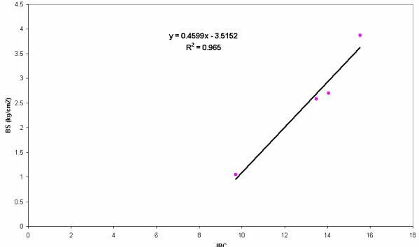
Figure 4. Bond Strength (BS) versus Joint Roughness Coefficient (JRC) for SST
Figure 4 shows an increasing linear relationship between the JRC and Bond strength as
BS = 0.4599 JRC ‑ 3.5152> R2 = 0.965
For this relation to be true JRC value must be greater than 8.
Effect of Tensile strength of rock on bonding strength of Shotcrete
In order to determine the effect of tensile strength of rock on bonding strength. Bond strength of shotcrete on different rock samples was determined and tensile strength of corresponding samples were also determined. It was found that tensile strength of rock does not have any relationship with bonding strength.
Table 4. Effect of tensile strength of rock on bonding strength of shotcrete
|
| Sample no |
rock type |
Bond failure load (kg) |
Area of Contact (cm2) |
Bond Strength (kg/cm2) |
Tensile Strength
(kg/cm2) |
|
| Rl |
fined grained |
120.5 |
82.51 |
1.460 |
2.124 |
|
sst |
|
|
|
|
| R2 |
medium grained sst |
89 |
88.664 |
1.003 |
1.05
|
| R3 |
Medium Grained sst |
220 |
85.63 |
2.57 |
3.87 |
| R7 |
Medium |
293.5 |
85.27 |
3.44 |
2.585 |
|
Grained Sst |
|
|
|
|
| R11 |
Medium |
54 |
86.75 |
.622 |
2.03 |
|
grained sst |
|
|
|
|
| R12 |
medium |
288 |
85.27 |
3.377 |
2.7 |
|
grained sst |
|
|
|
|
| R16 |
fined |
77 |
81.07 |
.95 |
4.94 |
| |
grained sst |
|
|
|
|
|
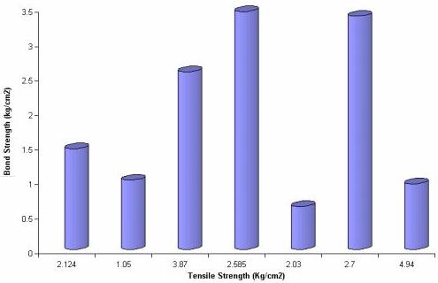
Figure 5. Bond Strength of Shotcrete versus Tensile Strength of Rock.
Effect of Time on Bond Strength
In order to determine the time effect on bonding strength. The bonding strength of shotcrete were determined on the same rock sample having smooth surface (JRC = 0.87)
Table 5. Effect of time on bonding strength of shotcrete
(rock sample : carbonaceous shale with JRC =1)
|
| Sample no |
Day |
Bond failure
Pull load(kg) |
Area of
contact (cm2) |
Bond Strength
(kg/cm 2) |
|
| R13 |
7th |
59 |
81.15 |
.727 |
| R13 |
14th |
212 |
81.15 |
2.584 |
| R14 |
21st |
241 |
82.03 |
2.96 |
| R14 |
28th |
245 |
81.42 |
3.012 |
|
It is seen that Bond Strength between the shotcrete and rock surface increases with the time till 21 days from the day of casting and beyond that time Bonding Strength remains constant.
Addition of accelerator in shotcrete mixture
A rock sample with plane surface (JRC = 1) was chosen Shotcrete were casted to the surface of rock sample by adding 5% sodium silicate to the shotcr6te mixture. The Bond Strength was determined for different day's interval. Table 6 and Figure 7 show the effect of accelerator on Bond Strength. It was found that by addition of accelerator the setting time for shotcrete mixture reduces. An early setting was achieved after 24 hours followed by a final setting was achieved after 5 days. An Increasing trend in bonding strength exists for first five days beyond which the bond strength remains unchanged for a given JRC.
Table 6. Effect of accelerator (5%sodium silicate) on Bond Strength of shotcrete
(Rock type fine grained white SST)
|
| Sample no |
Day of
testing |
Bond failure
Pull load (kg) |
Area of
Contact
(cm2) |
Bond
Strength
(kg/cm2) |
|
| R19 |
2nd |
28 |
81.159 |
.345 |
| R19 |
3rd |
106 |
81.538 |
1.30 |
| R19 |
4th |
172 |
81.472 |
2.11 |
| R19 |
5th |
237 |
81.164 |
2.92 |
| R19 |
7th |
240 |
81.081 |
2.96 |
|
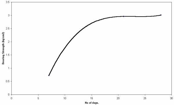
Figure 6. Bond Strength of shotcrete versus number of days.
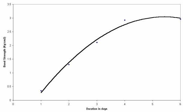
Figure 7. Effect of Accelerator (5% Sodium Silicate) on Bond Strength of Shotcrete.
Conclusion
It can be emphasized that bond strength is very sensitive to a particular range of JRC between 8 ‑ 17. The bonding strength increases linearly with an increase in the JRC.
BS = 0.4599 (JRC) - 3.5152 R2 = 0.965
Note This equation holds for the JRC range of 8 to 17, below which the effect of rock roughness on bonding strength is not significant.
There is no any effect of tensile strength of on bonding strength of shotcrete. This proves that JRC may be the main influencing factor on bond strength between the shotcrete and the rock surface, for a given casting parameters and the shotcrete mixture.
To achieve the maximum Bonding Strength, a minimum of 21 days is required for the ultimate setting of shotcrete.
To gain an early setting of shotcrete mixture accelerator must be added to shotcrete Addition of accelerator to shotcrete mixture reduces the setting time of shotcrete. The ultimate setting is achieved after 5 days.
REFERENCES
- Bekaert N.V., 1996, Tunneling the World. Dramix.
- Bondis S., Lumsden A. C. & Barton N R, 1981; Experimental studies of the Shear behavior of Rock Joints ;Int. J. Rock Mech. Min. Sci. & Geomech. Abstr. 18: 1‑21
- Chowdhary A.H., Ghosh A. & Hsiung S.M. 1995, On Natural Rock Joint Profile
Characterization using Self ‑ affine Fractal Approach. Rock Mechanics,
Daemen & Schultz(eds),
- Ferreo A.M. 1990, Geostatical description of the joint surface roughness. Rock Mechanics.; Contributions and challenges Mustrulid & Johnson 31st U . ~. Symp. Rock Mech. 1990 Balkema. 436‑467.
- Hahn T. & Holmgren J. 1979.; Adhesion of shotcrete to various types of Rock surfaces; Proc to IV.Int. congress on Rock Mechanics ; Montrecex 431‑439.
- Heping Xie, 1995 : Fractal Estimation of joints roughness coefficients . Fractured and jointed Rock masses Myer. cook, Goodman & Tsang. 1995 Balkema.205 ‑211
- Huang S.L. Oelfke S.M & Speck C, 1992,Applicability of Fractal Characterization and Modelling to Rock joint Profiles, Int. J. Rock Mech. Min. Sci. & Geomech Abstr. 29 : 89‑98.
- Suggested Method for Quantitative Description of Discontinuities, 1978, fnt. J. Rock Mech. Min. Sci. & Geomech. Abstr. 15 : 339‑346.
- Lee. H., Carr, Barr J. & Haas J 1990. The Fractal Dimension as a Measure of the Roughness of Rock Discontinuity profiles, Int. J. Rock Mech. Min, Sci. Geomech.
Abstr. 27 : 453‑464.
- Mahar J. W., Parker H. W 1975 ; Shotcrete Practice in u/g Constr. US Dept of Transportation Report no FRAOR &D73‑90 Avialable from NTIS: 56105
- Milne D. 1990, standardized joint descriptions for improved rock classification
- Rock Mechanics Contribution and challenges, Hustrulid & johnson. 31st US Symp. Rock Mech. 1990 Balkema: 35‑41.
- Singh U. K. et al 1998, Development of fibre reinforced shotcrete for supporting u/g opening against failure due to rock disc. and induced stresses. (Funded from coal S & T Grant of Dept. of Coal MT/88/94)